IEC 61000-4-5 defines test methods for evaluating the surge immunity of electrical and electronic equipment when subjected to high-energy disturbances caused by switching and lightning transients. This standard applies to equipment installed in different environments, including residential, commercial, light industrial, and industrial locations.
LISUN supplies the fully test solutions for the following IEC 61000-4-5, please see the below excel table:
| IEC 61000-4-5 Clause and Subject | LISUN Model |
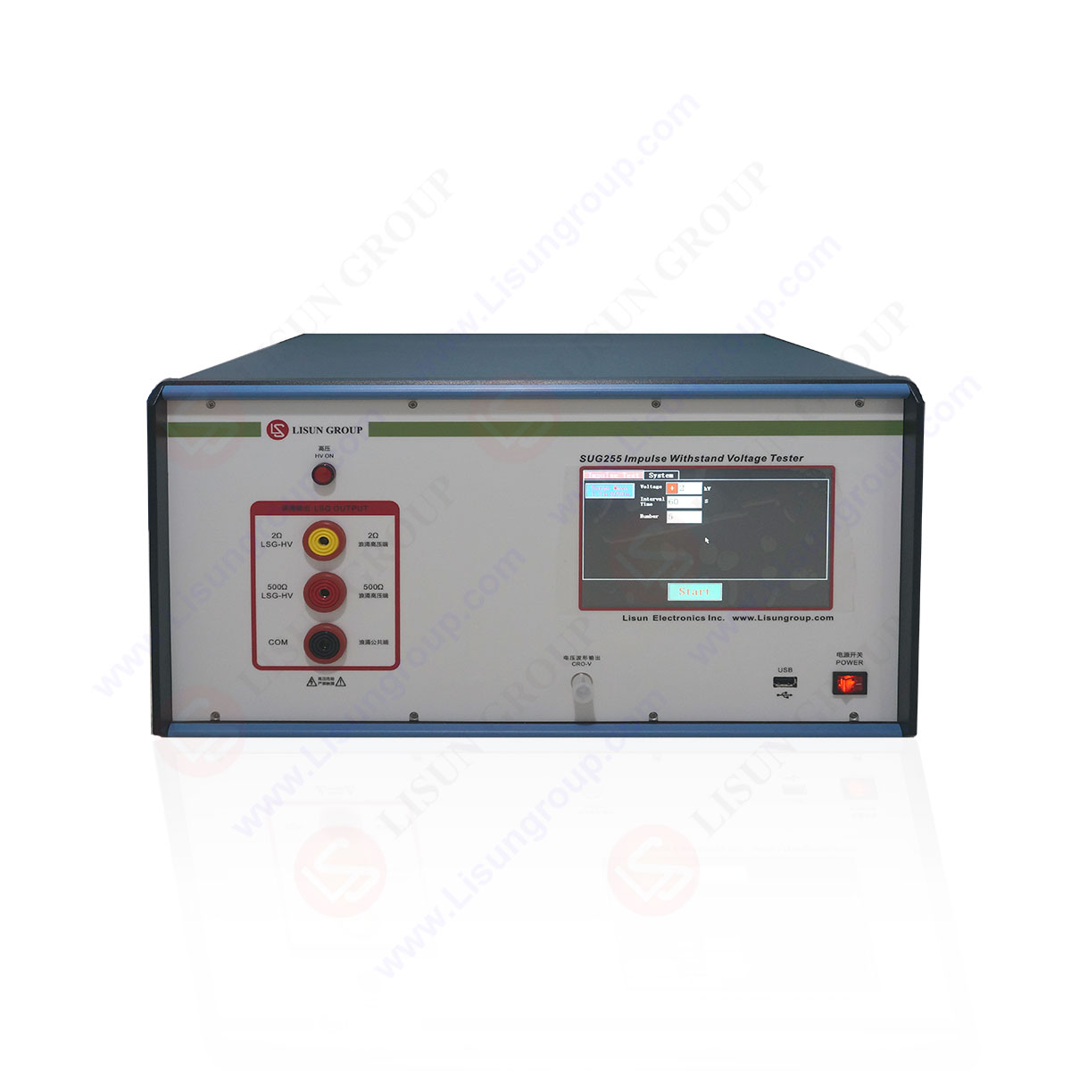
| 3.1.4 Combination Wave Generator | SG61000-5 and SG61000-5C |
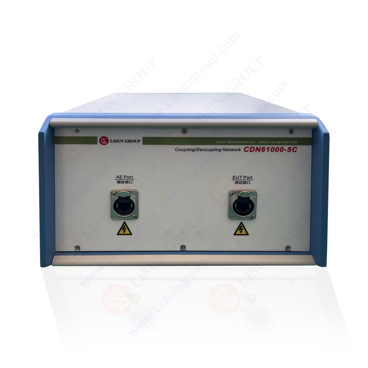
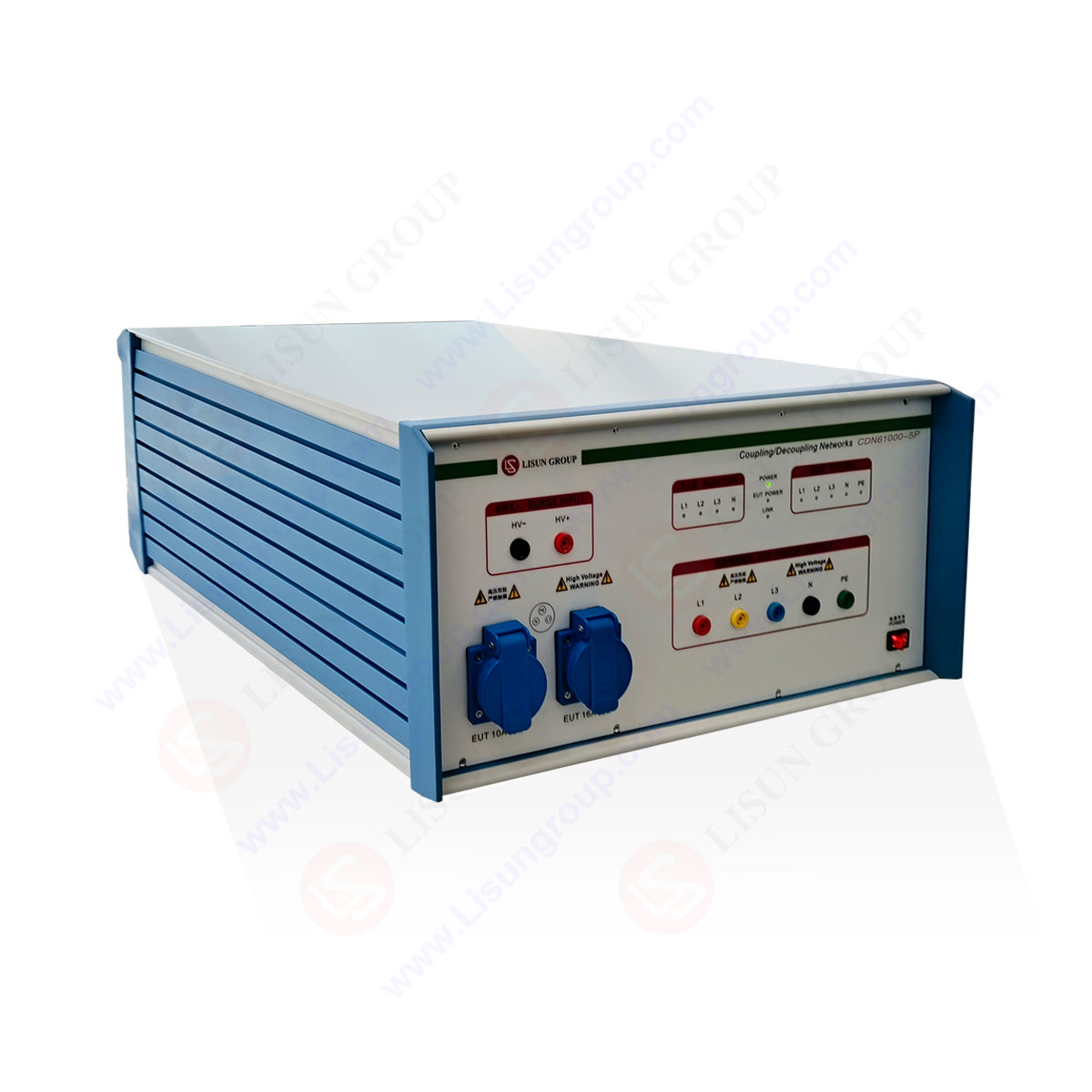
| 3.1.6 coupling/decoupling network | CDN61000-5C and CDN61000-5P |
| 6.2 1.2/50μs combination wave generator(Figure 1, Figure 2, Figure 3) | SG61000-5 |
| Annex A.2 10/700μS Combination Wave Generator (Figure A.1, Figure A.2, Figure A.3) | SUG-CCITT-A |
Your email address will not be published. Required fields are marked *

 中文简体
中文简体