In 2019, ANSI and IESNA jointly released the ANSI/IES LM-79-19 standard, establishing a critical benchmark for the LED solid-state lighting (SSL) industry. Over five years later, in 2025, the lighting industry is once again undergoing a major transformation with the release of the latest version of the LM-79 standard – ANSI/IES LM-79-24 – jointly issued by the American National Standards Institute (ANSI) and the Illuminating Engineering Society (IES). This updated standard provides more precise and standardized methods for testing the photometric and electrical performance of LED SSL products, and is expected to have a far-reaching impact on related industries worldwide.
As a foundational standard in the SSL lighting field, the importance of the LM-79 test method cannot be overstated. Globally, it serves as a key reference for energy efficiency certification programs across numerous countries—such as Energy Star, DOE, CEC, and DLC in the United States; VEET and IPART in Australia; ORDINANCE No. 62 and ORDINANCE No. 69 in Brazil; COA in Malaysia; and NOM in Mexico. LM-79 functions as an industry benchmark, measuring the quality of LED SSL products and guiding the direction of industry development.
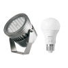
As companies actively respond to evolving standards, professional testing equipment becomes essential. As a leading brand in the industry, LISUN is committed to providing customers with high-quality, high-precision testing solutions. Its LSG-6000 LM-79 Moving Detector Goniophotometer (Mirror Type C), along with the LPCE-2 High Precision Spectroradiometer Integrating Sphere System, demonstrate significant advantages in meeting the requirements of the new LM-79 standard. These advanced systems offer comprehensive and robust support to enterprises striving to stay compliant and competitive.

LPCE-2(LMS-9000)High Precision Spectroradiometer Integrated Sphere System
The release of ANSI/IES LM-79-24 is expected to have a ripple effect, gradually influencing numerous related certification programs. We will continue to closely monitor developments and provide the latest updates as they emerge. Compared to the previous version, LM-79-24 introduces several key revisions:
Normative References:
The section on normative references has been revised to reflect current standards. These updates ensure that testing procedures align with the latest technologies and methodologies in the industry, enhancing both the credibility and relevance of test results.
Introduction of a New Concept – Photometric Center:
The definition section now includes the innovative concept of the photometric center, defined as:
“The point in a light source from which the inverse-square law operates most closely in the direction of maximum intensity.”
This clarification allows for a more precise description of light source characteristics and introduces a new dimension for in-depth optical performance evaluation.
Adjustment to Circuit Capacitance Requirements:
The permissible capacitance value in test circuits has been relaxed from “≤1.5 nF” to “≤2.0 nF”. This change likely reflects efforts to enhance compatibility with various circuit types or to accommodate emerging trends in circuit design.
Simplified Total Harmonic Distortion (THD) Data Collection:
The requirement for THD harmonic data collection using 1 MHz instruments—previously mandated to span orders from 2 to 100—has been revised. Now, all instruments must uniformly collect harmonic data from orders 2 to 50. This simplification streamlines the testing process, increases efficiency, and improves comparability across different measurement systems.
Enhanced Guidance on Luminous Flux Testing Principles:
The standard now includes a detailed explanation of the Integrated Angular Measurements method for luminous flux testing. This addition provides a clearer theoretical foundation, helping practitioners better understand the scientific logic behind the testing procedures and improving accuracy and consistency in measurement.
Streamlined Appendices:
Descriptions of “Airflow Considerations for Testing SSL Products” and “Power Supply Resistance and Inductance Interval” have been removed from the Annex. These deletions aim to make the standard more concise and focused, reducing unnecessary content and improving usability for practitioners.
The ANSI/IES LM-79-24 standard provides clear definitions regarding the scope of applicability for products. LED luminaires, integrated LED bulbs, integrated OLED bulbs, externally driven LED bulbs that comply with the ANSI standard circuit definitions or those specified by manufacturers as non-integrated LED bulbs, as well as LED light engines, are all covered by the standard. However, SSL products requiring external heat sinks, components of SSL products (such as LED packages or LED arrays), and housings or luminaires designed as SSL products but sold without a light source (often measured using relative photometry) are not subject to this standard.
In terms of testing parameters, the standard thoroughly considers both optical and electrical parameters. The optical parameters include total luminous flux (lm), luminous efficacy (lm/W), light intensity distribution, chromaticity coordinates, correlated color temperature (CCT), color rendering index (CRI), radiant intensity, radiant intensity distribution, photon flux, photon flux distribution, radiant flux, photon efficiency, and luminous efficiency. These parameters describe the optical performance of the product from various angles and are key indicators for evaluating lighting quality. The electrical parameters cover RMS AC voltage, RMS AC current, AC active power, power factor, total harmonic current distortion, voltage frequency, DC voltage, DC current, DC power, and others, providing an accurate assessment of the product’s performance under electrical drive. These parameters are crucial for evaluating energy efficiency and stability. LISUN LSG-6000 Moving Detector Goniophotometer (Mirror Type C) manufactured by LISUN completely meets LM-79-24、LM-79-19, COMMISSION DELEGATED REGULATION (EU) 2019/2015, CIE-121, CIE S025, SASO 2902, IS16106 and EN13032-1 clause 6.1.1.3 type 4 requirements. LSG-6000 is the latest upgraded product of LSG-5000 and LSG-3000 in compliance with the requirements of the LM-79-19 standard Clause 7.3.1. It’s an automatic light distribution intensity 3D curve testing system for measuring light. The darkroom can be designed according to the customer’s existing room size.

The release of the ANSI/IES LM-79-24 standard undoubtedly injects new vitality and regulation into the LED solid-state lighting industry. This update will affect manufacturers, testing institutions, and consumers alike. All stakeholders need to closely monitor changes in the standard and actively adjust strategies to meet the new requirements of industry development, working together to promote a brighter future for the LED solid-state lighting industry.
Comparison between old and new versions
ANSI/IES LM-79-24 has changed in many aspects compared with the previous version, as follows:
| NO. | Compare Projects | ANSI/IES LM-79-19 | ANSI/IES LM-79-24 | Differences |
| 1 | Standards | 2.1 ANSIIES RP-16-17《Nomenclature and Definitions for Illuminating Engineering》. | ANSUIESLS-1-22 《Lighting Science – Nomenclature and Definitions for Illuminating Engineering》 | Update of reference standards, including the definition of lighting engineering terms, total luminous flux measurement, goniometer measurement, etc. |
| 2.2 IESLM-78-17《IES Approved Method for Total Luminous Flux Measurement of Lamps Using an Integrating Sphere》. New York: Iluminating Engineering Society, 2017. For measurements using an integrating sphere system, the laboratory shall meet the requirements stated therein. | 2.2 ANSI/IESLM-78-20《Approved Method: Total Luminous Flu Meosurement of Lamp Using an Integting Sphere Photomee》. New York: lluminating Engineering Society:2020. For measurements using an integrating sphere system the laboratory shall meet the requirements stated therein | |||
| 2.3 IES LM-75-01/R12《IES Guide to Gonlometer Measurements, Types,and Photometrk Coordinate Systems》. New York: luminating Engineering Society; 2012. For measurements using a goniometer system, the laboratory shall meet the requirements stated therein. | 2.3 ANSIIES LM-75-19《Approved Method Guide to Goniometer Measurments and Types, and Photome Coordinate Systems》. New York:illuminating Engineering Society: 2019 For measurements using a goniometer system, the labortary meet requirement stated therein | |||
| 2 | Definition | 3.3 photometric center:The point in alight source from which the inverse square law operates most closely inthe drection of max mum intensity. (See ANSIIESLM-75-19,Section 3.28) | Added the concept of “photometric center” to more accurately describe the characteristics of the light source | |
| 3 | Test circuit capacitance value | 5.2.1.2 Maximum Test Circuit Capacitance. capaditance of the test circuit,not indluding the supply,shall be less than 1.5 nanofarads (nF).Th circuit capacitance shall be determined by measuring capacitance across the wires intended to be connected to the AC power supply terminals. | 5.2.1.2 Maximum Test Circuit Capacitance.The capacitance of the test circuit, not indluding the power supply,shall be less than2.0 nanofarads (nF).The test circuit capacitance shall be determined by measuring the capacitance across the wires intended to be connected to the AC power supply terminals. | The capacitance value requirement of the test circuit has been relaxed from ≤1.5nF to ≤2.0nF |
| 4 | Total harmonic distortion acquisition magnitude | 5.3.4 Total Harmonic Distortion Measurement Total harmonic distortion(THD) shall be calculate as the RMS summation of the harmonic components (orders of magnitude of 2 to 50 for a 100-kHz r and orders of magnitude of 2 to 100 for a 1-MHz n as a minimum) divided by the fundamental frequency during operation of the DUT. | 5.3.4 Total Harmonic Distortion Measurements. Total harmonic distortion (THD) shall be calculated as the RMS summation of the harmonic components (orders of magnitude of 2 to 50, as a minimum) divided by the fundamental frequency during operation of the DUT. | Deleted the requirement that the harmonic acquisition level of 1MHz instruments should be at least 2 to 100, and unified the requirement that the harmonic acquisition level of all instruments should be 2 to 50. |
| 5 | Luminous flux test principle | 9.4 Integrated Angular Measurements An integrated mesurement over a specificed solid angle is simply the integration of smaller sold angles weighted by the measurement quantity. For example, the total luminous flux is calculated by using | Added the luminous flux of light distribution Integrated Angular Measurements Test principle description | |
| 6 | Appendix Contents | Anex A-Airow Considerations for Teting SSL Products Annex B-High Frequency Current and Measurement Circult Cap Annex C-Power Supply Resistance and Inductance Dependen Annex D -Tolerance Interval vs. Aceptance Interval………. AnnexE-Benefts of Wareform Measurement. Annex F-Lower Luminous intensity for Chromticity Uniormity | Annex A – High Frequency current and measurement Circuit capacitance Annex B – Tolerance internal vs Acceptance interval Annex C- Benefits of Waveform Measurement Annex D Lower Luminous for Chromaticity uniformity | Deleted the contents of “Airflow Considerations For Testing SSL Products” and “Power Supply Resistance And Inductance Interval” in the appendix. |
Tags:LPCE-2 (LMS-9000) , LSG-6000
Your email address will not be published. Required fields are marked *

 中文简体
中文简体