The IEC 61439-1 standard, titled “Low-voltage switchgear and controlgear assemblies – Part 1: General rules”, specifies the general requirements for low-voltage switchgear and controlgear assemblies. It applies to assemblies with rated voltages up to 1000V AC or 1500V DC and is intended to ensure the safety, reliability, and performance of such assemblies.
IEC 61439-1: 2011 Low-voltage switchgear and controlgear assemblies – Part 1: General rules
LISUN supplies the fully test solutions for the following IEC 61439-1: 2011 , please see the below excel table:
| IEC 61439-1 Clause and Subject | LISUN Model |
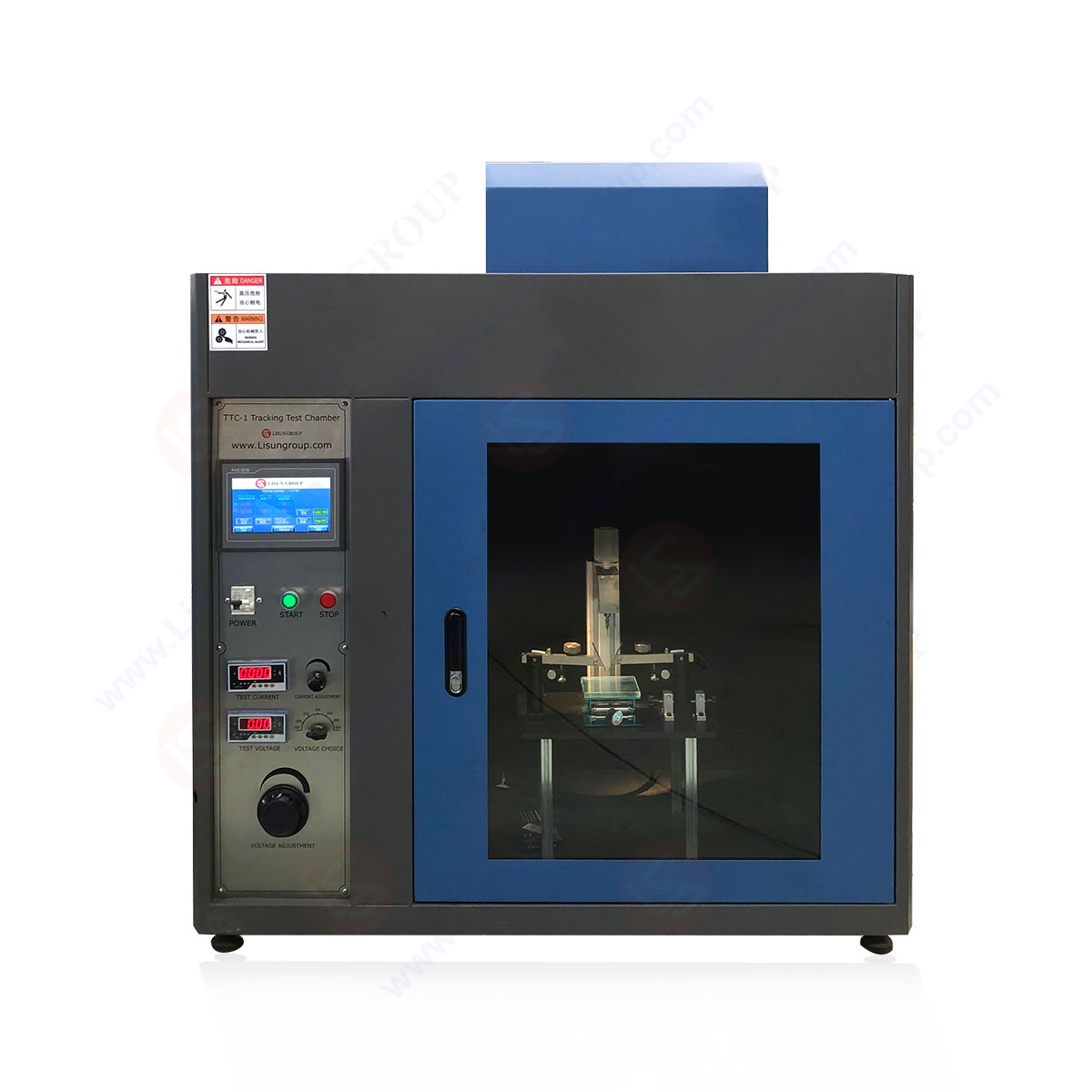
| 3.6.15 &3.6.16 Comparative tracking index | TTC-1 |
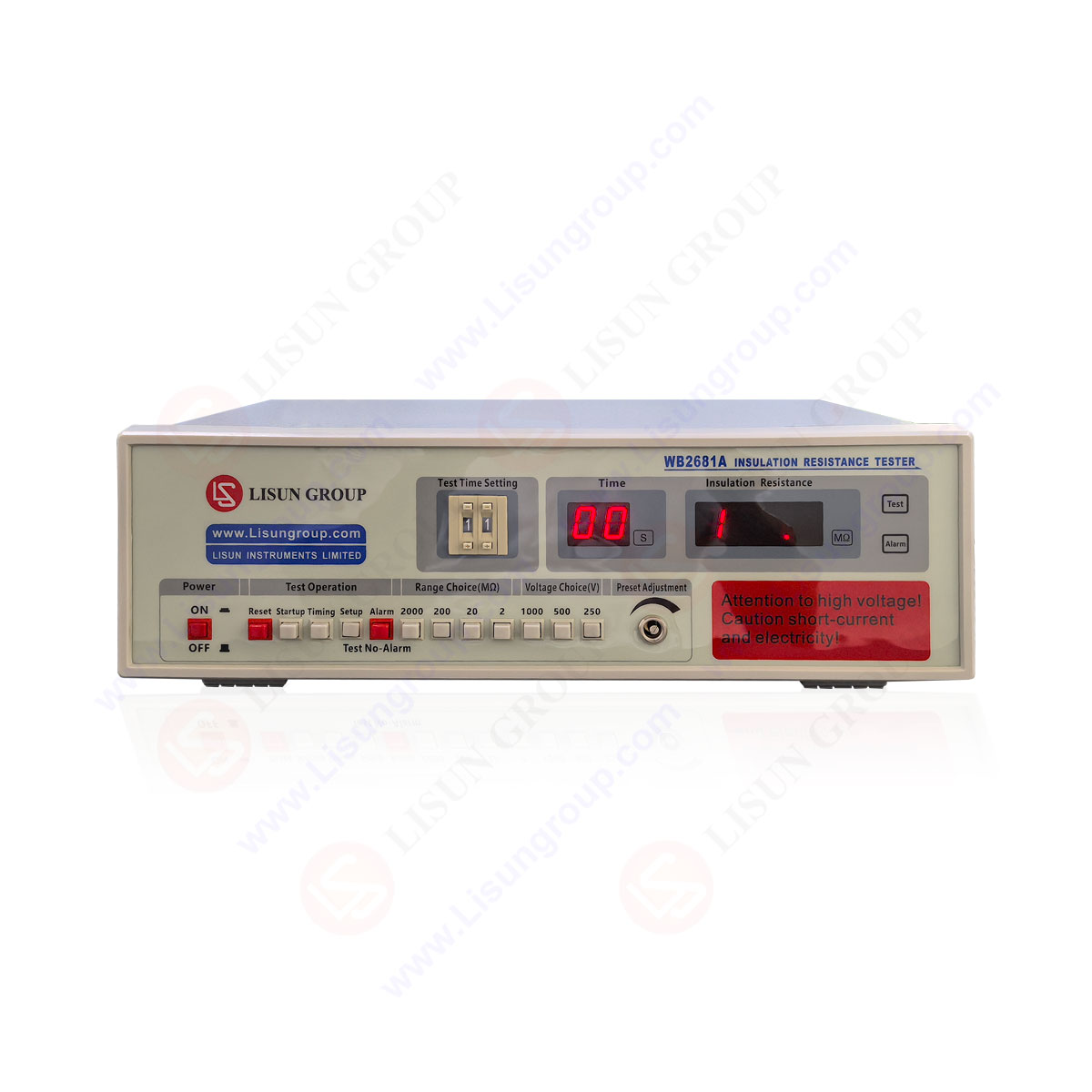
| 3.6.17 Disruptive discharge | WB2681A |
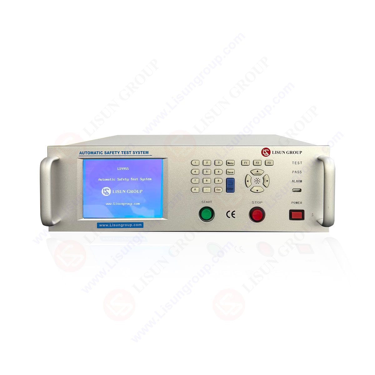
| 3.7 Protection against electric shock | LS9955 |
| 3.8.9.3 Insulation Voltage | WB2681A |
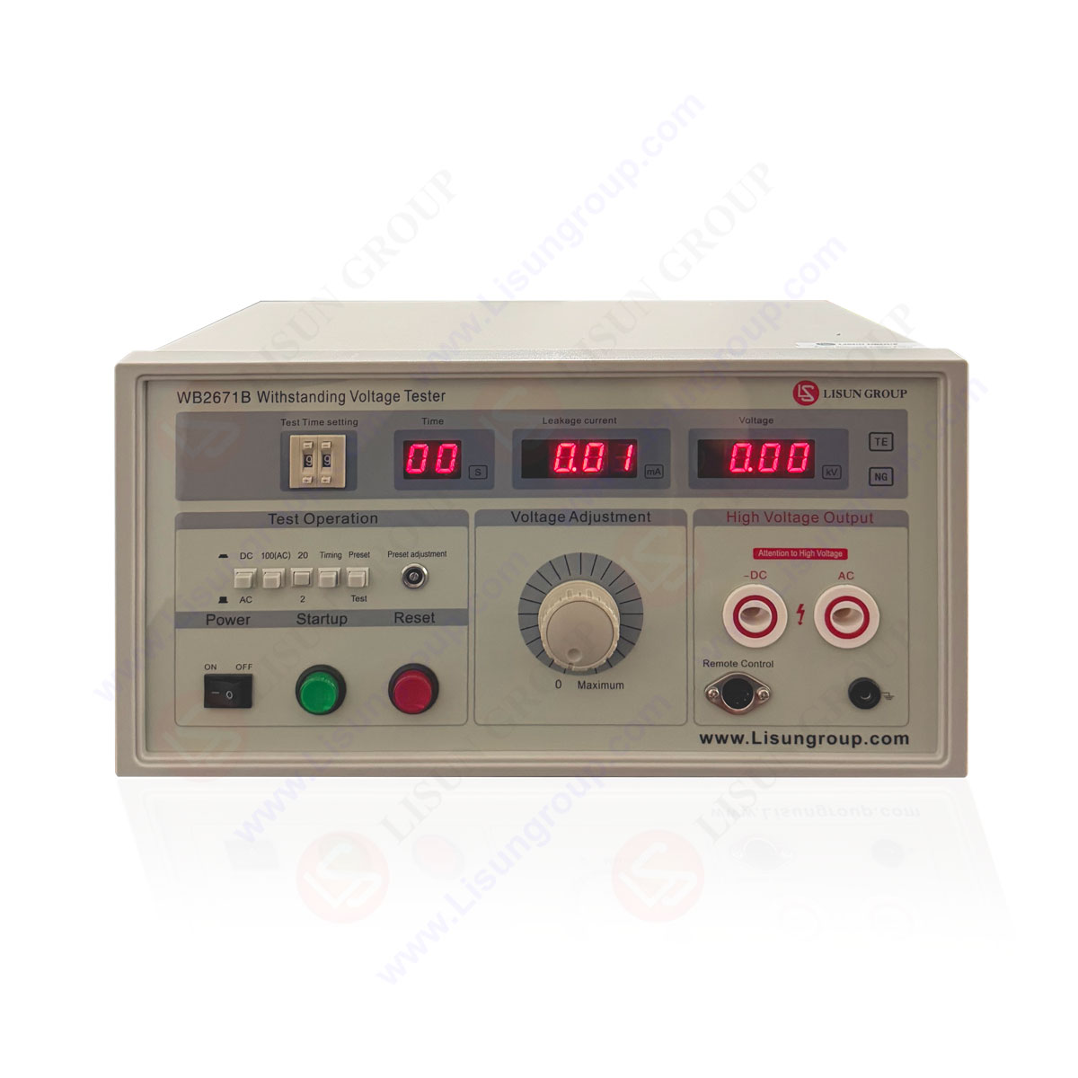
| 3.8.9.4 Impluse withstand voltage | WB2671 |
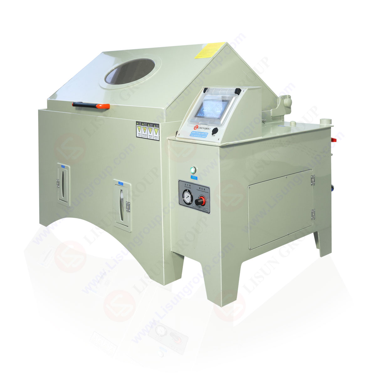
| 8.1.2 (10.2.2)Protection against corrsion | YWX/Q-010 |
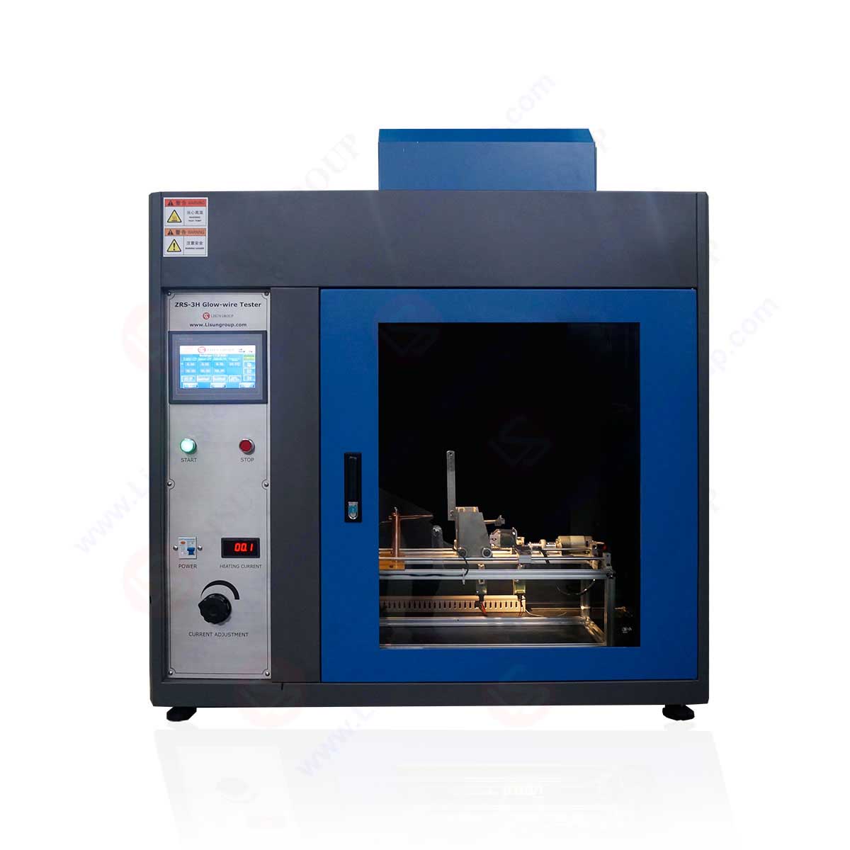
| 8.1.3.2.3 Resistance of insulating material to abnormal heat and fire due to internal electric effect | ZRS-3H and ZY-3 |
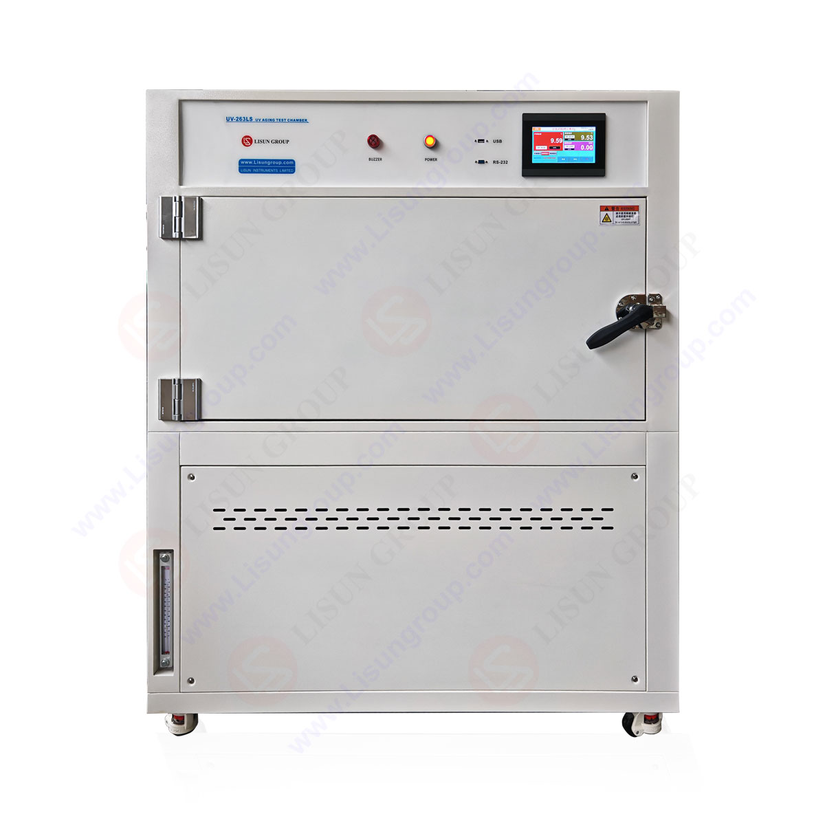
| 8.1.4(10.2.4) Resistance to ultra-violet radiation | UV-263LS |
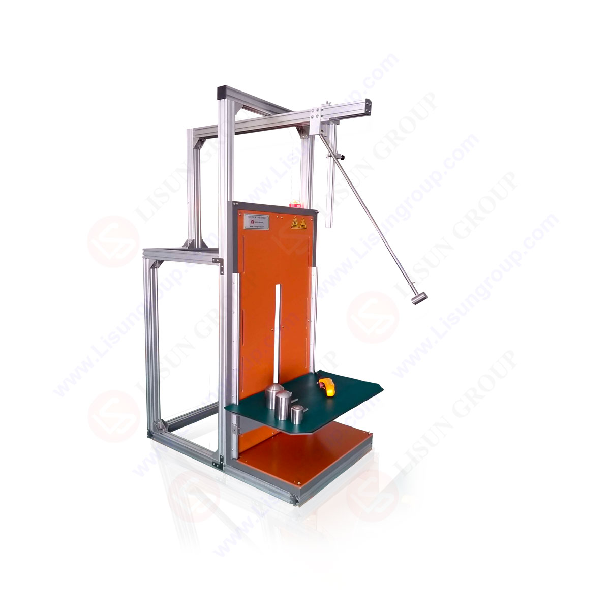
| 8.2.1(10.2.6) Protection aganst mechanical impact | IK07-10 |
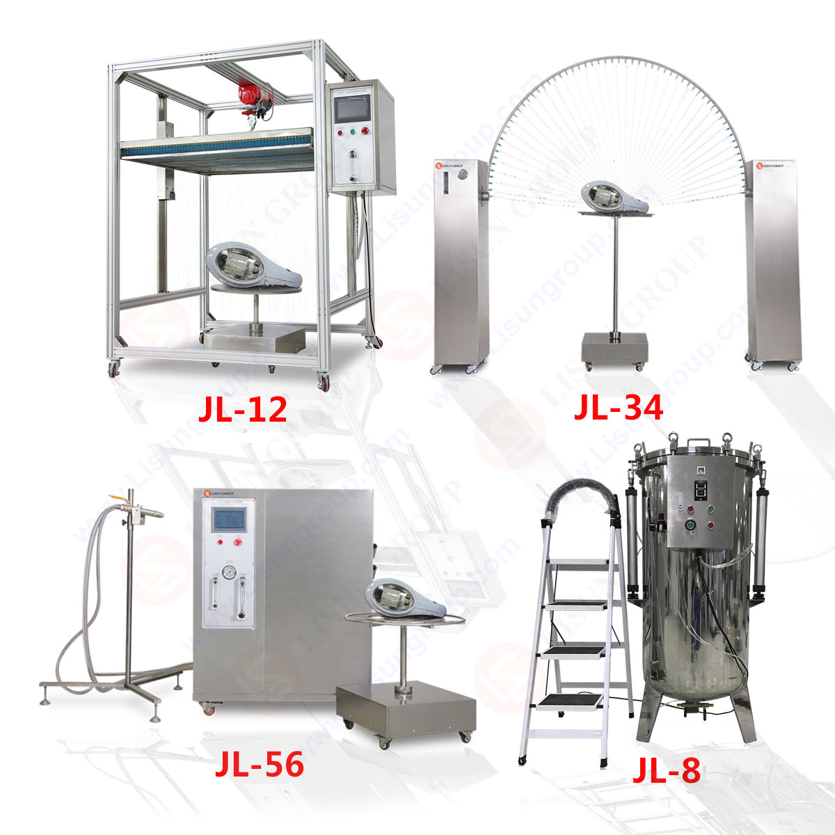
| 8.2.2(10.2.6) protection against contact with live parts, ingress of solid foreign bodies and water | JL-12 and JL-34 |
| 8.3.3 Creepage disctance | CK-1 |
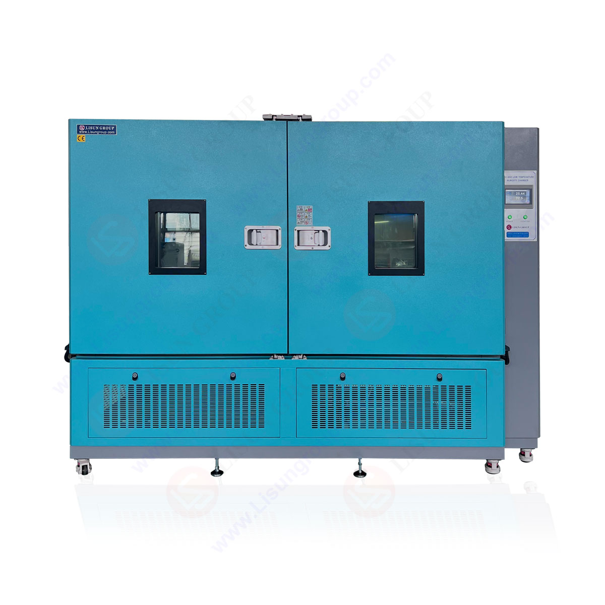
| 10.2.2.2 Thermal Chamber | GDJS-015B |
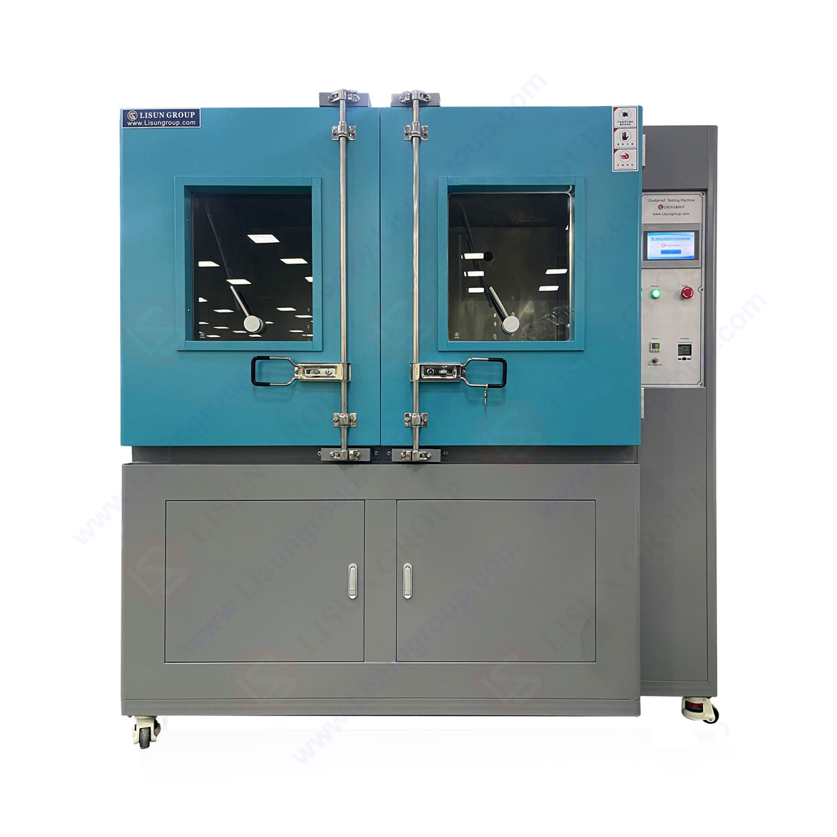
| 10.3 Degress of protection of IP test | JL-12 and JL-34 and JL-56 and SC-015 |
| 10.5 Protection against electric shock | LVD-100KG |
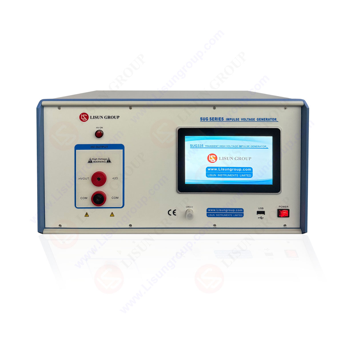
| 10.9.3 Impluse withstand voltage | SUG255 |
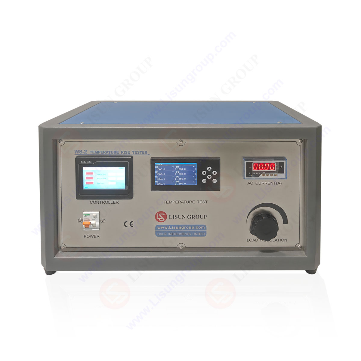
| 10.10(9.2) Verfication of temperature rise | WS-1 |
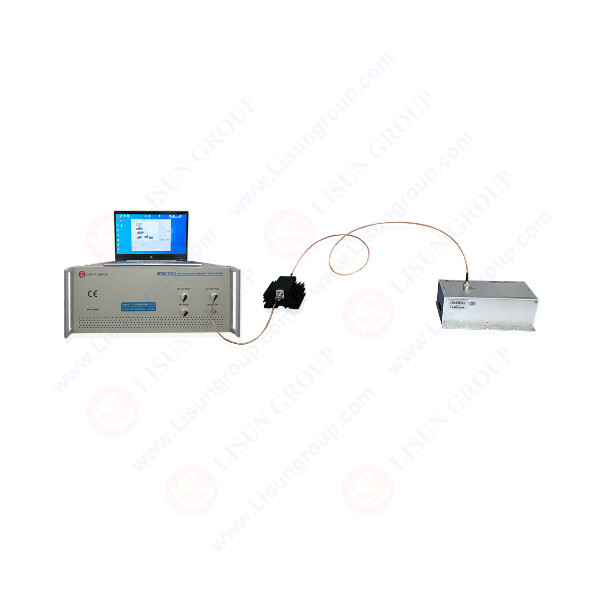
| J.9.4.3 Immunity | RFCI61000-6 |
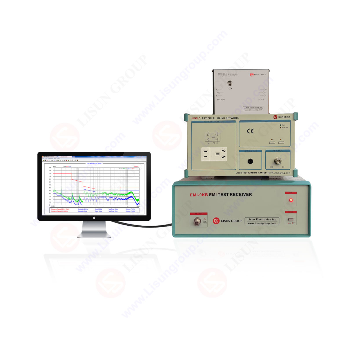
| J.9.4.4 Emission | EMI-9KB |
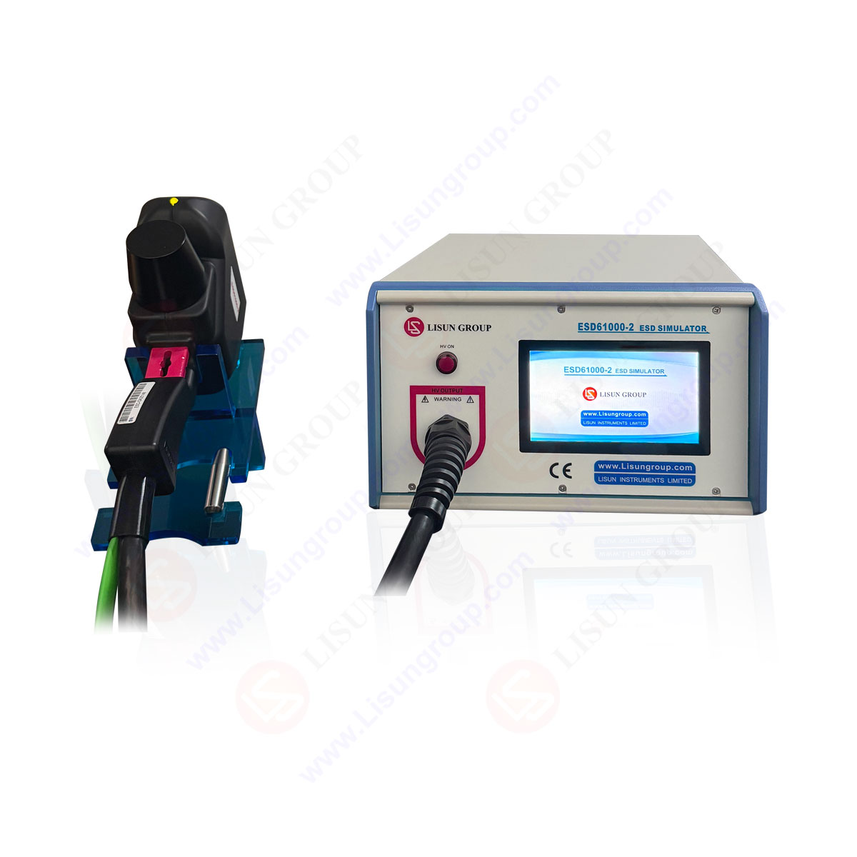
| J.10.12.1(Table 1 and Table 2) | ESD61000-2 |
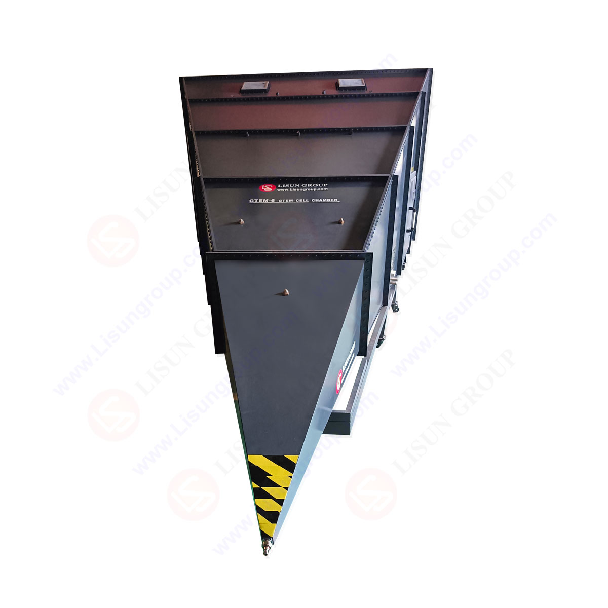
| GTEM-2 | |
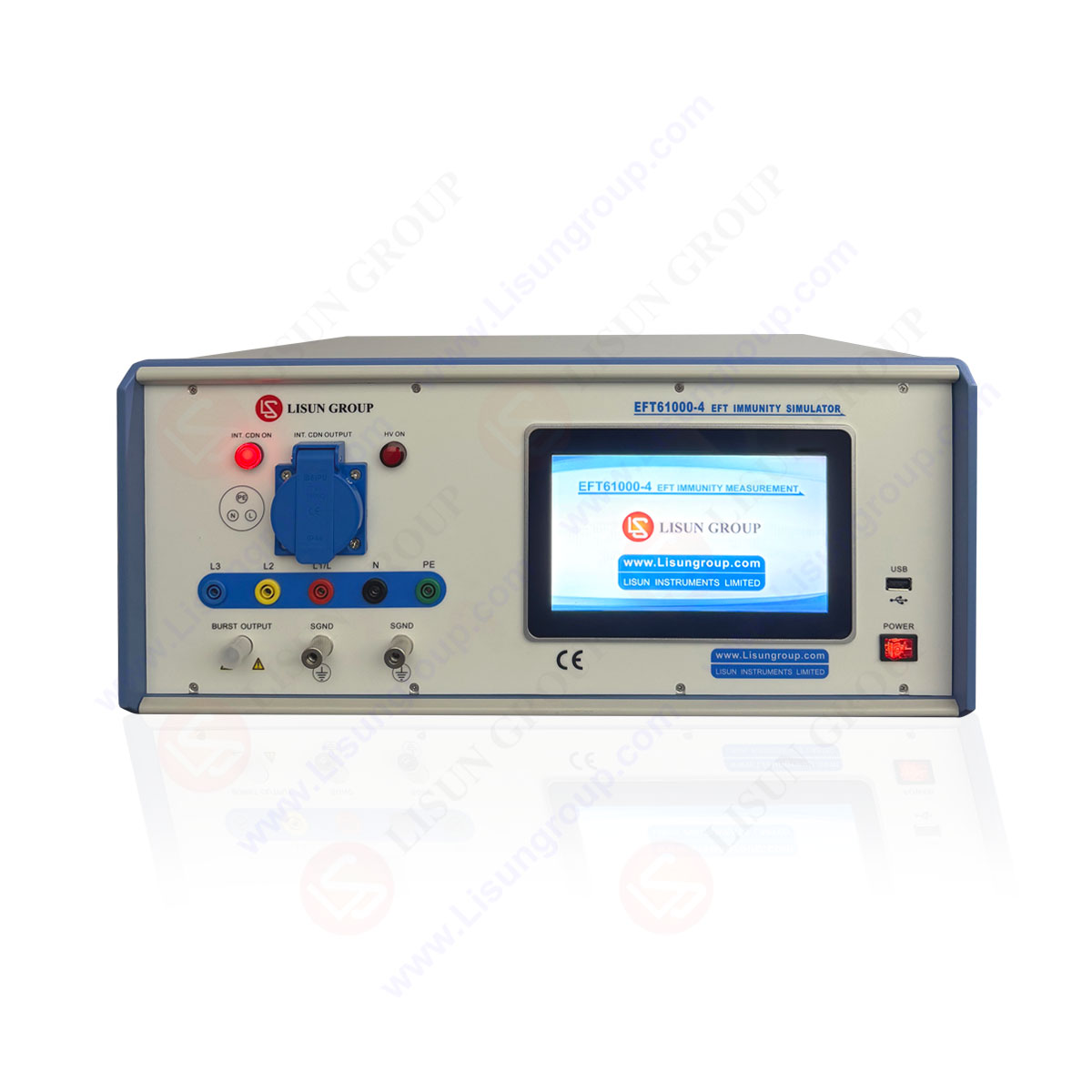
| EFT61000-4 | |
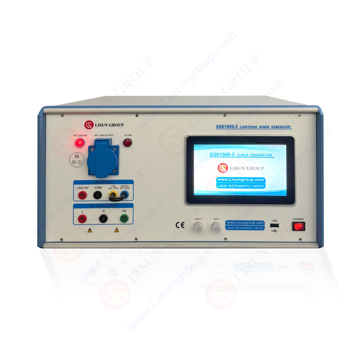
| SG610000-5 | |
| RFCI61000-6 | |
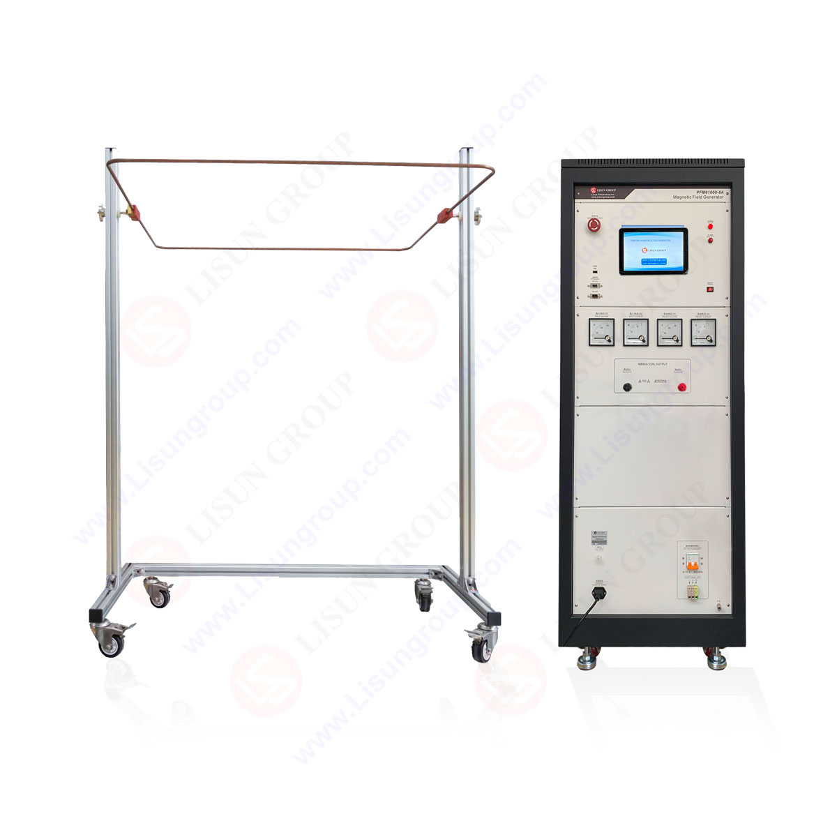
| PFM61000-8A | |
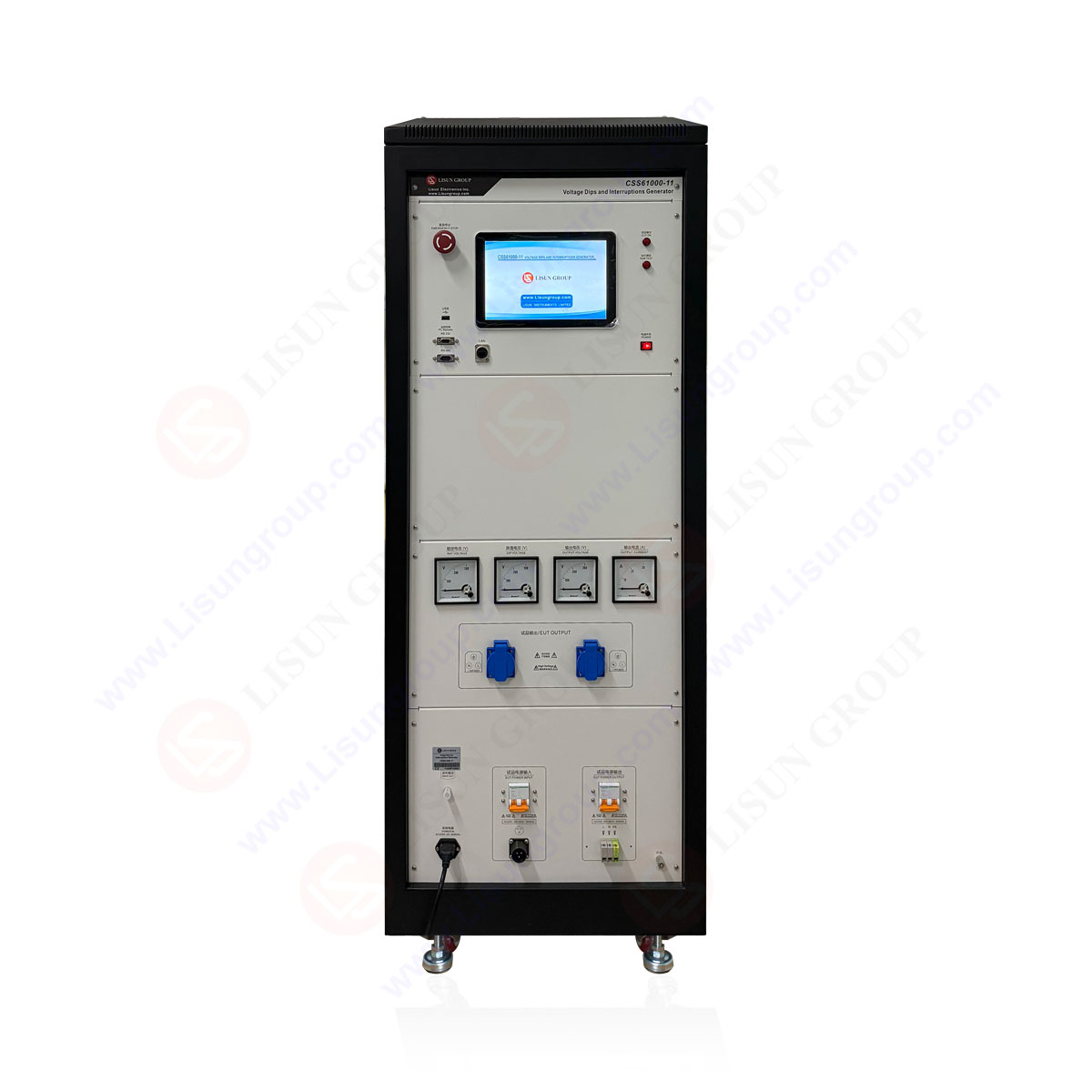
| CSS61000-11 |
Your email address will not be published. Required fields are marked *

 中文简体
中文简体